This article introduces the development framework based on the gateway, using Ubuntu as a Bluetooth gateway to access the Tuya IoT platform, and enabling access to Tuya's Bluetooth Mesh & LE sub-devices.
Hardware Preparation
- ZS3L module
- USB to serial port adapter
- Tuya's Bluetooth Mesh & LE sub-devices
Hardware Connection
Refer to the ZS3L module specification sheet and connect the ZS3L and USB to serial port pins according to the corresponding relationship in the table below.
| ZS3L | USB to serial port |
|---|---|
| TX | RX |
| RX | TX |
| RTS | CTS |
| CTS | RTS |
After the hardware is connected, plug the USB to serial port adapter into the USB port of the PC, and use the code in the Appendix to read the firmware version number of the ZS3L module to check whether the hardware connection is normal.
Create Product
Devices that connect to the Tuya IoT platform have a unique Product ID (PID), which is obtained by creating a product on the Tuya IoT platform. Therefore, you need to create a product for the gateway, define the functions of the gateway, and select the App panel of the gateway. For detailed operating steps, please refer to Create Product.
Note that when creating a Bluetooth gateway product, the protocol type should be selected as Bluetooth Mesh(SIG).
Program Development
Download the Development Package
The steps to download the gateway development package are as follows:
Install and log in to the IDE plugin in Visual Studio Code. For specific operations, please refer to Tuya Wind IDE.
Click New Development Framework on the homepage of Tuya Wind IDE. Select TuyaOS SDK mode for development mode, Gateway device development package for package type, and Soc/ubuntu/Linux/X86_64 for development platform.
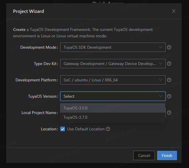
Select the latest version and click Complete to start downloading the development package.
After the development package is downloaded, the project will be automatically opened in Visual Studio Code, and its directory structure is as follows:
| Name | Description |
|---|---|
| apps | Application examples, that is, product development packages |
| build | Compilation configuration directory, which stores compilation configuration files (you don't need to pay attention to it). |
| build_app.sh | Compilation script |
| docs | Doxygen interface documentation |
| include | Header file |
| libs | Library file |
| Makefile | Makefile file |
| output | Compilation output directory, where the generated program is located in the output/<application project name>_<version number> path. |
| scripts | Compilation framework (you don't need to pay attention to it). |
| vendor | Development environment. The development environment is downloaded online to the local machine during compilation. |
Compile the Application
You can use tuyaos_demo_blemesh to develop Bluetooth gateway products, which contains the functions of the Bluetooth gateway. Right-click tuyaos_demo_blemesh under the apps directory in the IDE and click Build Project to compile.
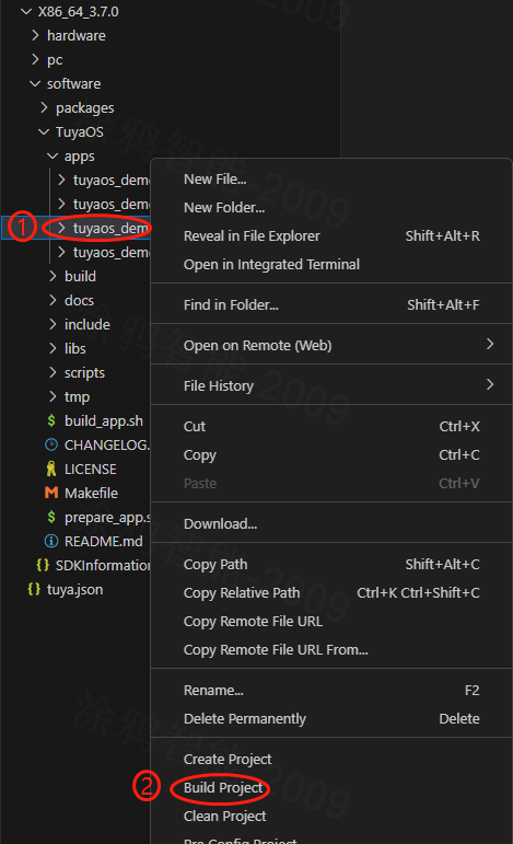
After successful compilation, an executable program will be generated in the output/tuyaos_demo_blemesh_<version number> directory.
Porting and Adapting
TuyaOS defines a standardized TuyaOS Kernel Layer (TKL), which aims to shield hardware and system differences and achieve cross-platform compatibility. Therefore, you need to complete the adaptation of TuyaOS on the Ubuntu platform, please refer to Porting Guide for details.
After the adaptation is completed, recompile the application.
Run the Application
There is a configuration file in the same-level directory of the executable program. You need to modify the configuration file. The modified content includes:
- Change the serial port device name to the serial port device name recognized by your PC for the USB to serial port adapter.
- Change
pidto the PID obtained by creating the product. - Change
uuidandauthkeyto the authorization information you are testing.
Modify the configuration file and save it, then run the executable program directly. Add the gateway through the Tuya Smart Life App, and add and control Bluetooth Mesh or Bluetooth LE sub-devices.
Notes
- You need to verify the connectivity of the hardware and be able to obtain the version number of the ZS3L module, otherwise the application will not work.
- TuyaOS-related TKL interfaces may vary across different products and require porting and adaptation, mainly by selecting network cards.
- PID, UUID, and AUTHKEY need to be changed to your own, and UUID and AUTHKEY cannot be reused. One machine must have one key.
<a id="appendix"></a>
Appendix
Code: Select all
/**
 * Instructions for use:
 *   1. Copy the contents and save them to the ncp_test.c file.
 *   2. Modify the macro definition TEST_UART_NAME to the serial port device corresponding to the ZS3L module.
 *   3. Compile
 *     $ gcc ncp_test.c -o ncp_test -lpthread
 *   4. Run the ncp_test program. If the module version can be read, the communication is normal; otherwise, check the serial port.
 *     Successful input print example:
 *     Send data[5:5]: 1a c0 38 bc 7e
 *     Recv data[128:7]: 1a c1 02 0b 0a 52 7e
 *     Send data[4:4]: 80 70 78 7e
 *     Ncp reset success.
 *     Send data[8:8]: 00 42 21 a8 53 dd 4f 7e
 *     Recv data[128:11]: 01 42 a1 a8 53 28 15 d7 c1 bf 7e
 *     Send data[4:4]: 81 60 59 7e
 *     Ncp set version success.
 *     Send data[9:9]: 11 43 21 57 54 39 51 2b 7e
 *     Recv data[128:14]: 12 43 a1 57 54 39 15 b3 59 9c 5a 7a 1c 7e
 *     Send data[4:4]: 82 50 3a 7e
 *     COO manuId:0001, version:1.0.8.
 */
#include <errno.h>
#include <fcntl.h>
#include <stdarg.h>
#include <stdio.h>
#include <stdlib.h>
#include <unistd.h>
#include <pthread.h>
#include <string.h>

#include <termios.h>
#include <sys/ttydefaults.h>

#define TEST_UART_NAME      "/dev/ttyS1"
#define TEST_UART_SPEED     115200
#define TEST_UART_STIO_BIT  1
#define TEST_UART_RTSCTS    TRUE
#define TEST_UART_FLOWCTR   TRUE

#define UART_DEBUG_PRINTF   1

typedef unsigned int bool;
#ifndef FALSE
#define FALSE 0
#endif

#ifndef TRUE
#define TRUE 1
#endif

#ifndef NULL
#ifdef __cplusplus
#define NULL 0
#else
#define NULL ((void *)0)
#endif
#endif

static const struct { int bps; speed_t posixBaud; } baudTable[] =
{ { 600, B600    },
  { 1200, B1200   },
  { 2400, B2400   },
  { 4800, B4800   },
  { 9600, B9600   },
  { 19200, B19200  },
  { 38400, B38400  },
  { 57600, B57600  },
  { 115200, B115200 },
  { 230400, B230400 } };

#define BAUD_TABLE_SIZE (sizeof(baudTable) / sizeof(baudTable[0]) )

// Define CRTSCTS for both ingoing and outgoing hardware flow control
// Try to resolve the numerous aliases for the bit flags
#if defined(CCTS_OFLOW) && defined(CRTS_IFLOW) && !defined(__NetBSD__)
  #undef CRTSCTS
  #define CRTSCTS (CCTS_OFLOW | CRTS_IFLOW)
#endif
#if defined(CTSFLOW) && defined(RTSFLOW)
  #undef CRTSCTS
  #define CRTSCTS (CTSFLOW | RTSFLOW)
#endif
#ifdef CNEW_RTSCTS
  #undef CRSTCTS
  #define CRTSCTS CNEW_RTSCTS
#endif
#ifndef CRTSCTS
  #define CRTSCTS 0
#endif

#define ASCII_XON   0x11
#define ASCII_XOFF  0x13

// Define the termios bit fields modified by ezspSerialInit
// (CREAD is omitted as it is often not supported by modern hardware)
#define CFLAG_MASK (CLOCAL | CSIZE | PARENB | HUPCL | CRTSCTS)
#define IFLAG_MASK (IXON | IXOFF | IXANY | BRKINT | INLCR | IGNCR | ICRNL \
                    | INPCK | ISTRIP | IMAXBEL)
#define LFLAG_MASK (ICANON | ECHO | IEXTEN | ISIG)
#define OFLAG_MASK (OPOST)

static int  g_uart_fd    = -1;
static char g_ezspSeq    = 0;
static char g_ashFramNum = 0;
static char g_ashAckNum  = 0;
static char gcur_ezspSeq = 0;

static unsigned short halCommonCrc16(unsigned char newByte, unsigned short prevResult);

int ezspSetupSerialPort(unsigned char *uart_name, unsigned int bps, unsigned char stopBits, bool rtsCts, bool flowControl)
{
    int i = 0;
    struct termios tios, checkTios;
    speed_t baud;

    // Setting this up front prevents us from closing an unset serial port FD
    // when breaking on error.
    g_uart_fd = -1;

    while (TRUE) { // break out of while on any error
        for (i = 0; i < BAUD_TABLE_SIZE; i++) {
            if (baudTable[i].bps == bps) {
                break;
            }
        }

        if (i < BAUD_TABLE_SIZE) {
            baud = baudTable[i].posixBaud;
        } else {
            printf("Invalid baud rate %d bps\r\n", bps);
            break;
        }

        if ((stopBits != 1) && (stopBits != 2)) {
             printf("Invalid number of stop bits:%d.\r\n", stopBits);
            break;
        }

        g_uart_fd = open(uart_name, O_RDWR | O_NOCTTY | O_NONBLOCK);

        if (g_uart_fd == -1) {
             printf("Serial port open failed:%s\r\n", strerror(errno));
            break;
        }

        tcflush(g_uart_fd, TCIOFLUSH); // flush all input and output data

        //#define ANDROID_PLATEM
    #if 0//#ifdef ANDROID_PLATEM

        fcntl(*serialPortFdReturn, F_SETFL, 04000);
    #else
        fcntl(g_uart_fd, F_SETFL, FNDELAY);
    #endif

        tcgetattr(g_uart_fd, &tios); // get current serial port options

        cfsetispeed(&tios, baud);
        cfsetospeed(&tios, baud);

        tios.c_cflag |= CLOCAL; // ignore modem inputs
        tios.c_cflag |= CREAD; // receive enable (a legacy flag)
        tios.c_cflag &= ~CSIZE; // 8 data bits
        tios.c_cflag |= CS8;
        tios.c_cflag &= ~PARENB; // no parity
        if (stopBits == 1) {
            tios.c_cflag &= ~CSTOPB;
        } else {
            tios.c_cflag |= CSTOPB;
        }
        if (flowControl && rtsCts) {
            tios.c_cflag |= CRTSCTS;
        } else {
            tios.c_cflag &= ~CRTSCTS;
        }

        tios.c_iflag &= ~(BRKINT | INLCR | IGNCR | ICRNL | INPCK | ISTRIP | IMAXBEL | IXON | IXOFF | IXANY);

        if (flowControl && !rtsCts) {
            tios.c_iflag |= (IXON | IXOFF); // SW flow control
        } else {
            tios.c_iflag &= ~(IXON | IXOFF);
        }

        tios.c_lflag &= ~(ICANON | ECHO | IEXTEN | ISIG); // raw input

        tios.c_oflag &= ~OPOST; // raw output

        memset(tios.c_cc, _POSIX_VDISABLE, NCCS); // disable all control chars

    #if 0//#ifdef ANDROID_PLATEM
        tios.c_cc[VSTART] = ('q'&037);           // define XON and XOFF
        tios.c_cc[VSTOP] = ('s'&037);
    #else
        tios.c_cc[VSTART] = CSTART;           // define XON and XOFF
        tios.c_cc[VSTOP] = CSTOP;
    #endif

        tios.c_cc[VMIN] = The workflow of the code is as follows:

1. First, the program imports the necessary libraries: NumPy and Pandas.

2. It then reads in a CSV file (named 'data.csv' in this case) using the Pandas library's read_csv() function and stores it in a variable called 'data'. The CSV file contains a list of car models and their corresponding miles per gallon (mpg), horsepower, and weight.

3. The program then defines a function called 'normalize' that takes in a NumPy array (in this case, the 'data' variable) and normalizes each column to a range between 0 and 1. This is done to ensure that each feature has equal importance when training a machine learning model.

4. The program then calls the 'normalize' function on the 'data' variable and stores the normalized data in a new variable called 'normalized_data'.

5. Next, the program splits the data into a training set and a testing set using the train_test_split() function from the scikit-learn library. The training set contains 80% of the data, while the testing set contains the remaining 20%.

6. The program then defines a machine learning model using scikit-learn's LinearRegression class, which will be used to predict a car's mpg based on its horsepower and weight.

7. The model is trained on the training set using the fit() method, which takes in the features (horsepower and weight) and the target variable (mpg).

8. Once the model is trained, the program uses it to make predictions on the testing set using the predict() method. The predicted values are stored in a variable called 'predictions'.

9. Finally, the program calculates the mean squared error (MSE) between the predicted values and the actual values from the testing set. The lower the MSE, the better the model's predictions are.